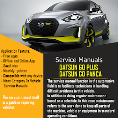
Service Manuals For Datsun Go
Contains ads
3.0star
30 reviews
1K+
Downloads

Everyone
info


About this app
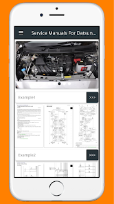
A service manual is a guide used in guiding service implementation that refers to factory service standards.
The contents of the service manual are:
Operating system: how to operate a device
Disassembly and assembly: the way or standard operating procedures for dismantling components
Testing and setting: how to calibrate and adjust the tool
Product Specifications: information specifications of the equipment made.
The function of the service manual in the automotive field is to make it easier to repair a vehicle when it is damaged, which is difficult to detect, to carry out regular maintenance based on a schedule. In this case maintenance refers to the work done to keep all parts of the machine, vehicle or equipment in standard operating conditions.
The service manual itself is a guide in repairing vehicles
"Periodic Maintenance" is maintenance that is carried out regularly based on a schedule.
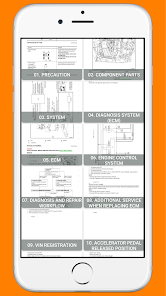
This service manual contains:
01. PRECAUTION
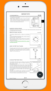
02. COMPONENT PARTS
03. SYSTEM
04. DIAGNOSIS SYSTEM (ECM)
05. ECM
06. ENGINE CONTROL SYSTEM
07. DIAGNOSIS AND REPAIR WORKFLOW
08. ADDITIONAL SERVICE WHEN REPLACING ECM
09. VIN REGISTRATION
10. PEDAL RELEASED POSITION LEARNING ACCELERATOR
11. THROTTLE VALVE CLOSED POSITION LEARNING
12. IDLE AIR VOLUME LEARNING
13. MIXTURE RATIO SELF-LEARNING VALUE CLEAR
14. BASIC INSPECTION
15. FUEL PRESSURE CHECK
16. HOW TO SET SRT CODE
17. TROUBLE DIAGNOSIS - SPECIFICATION VALUE
18. POWER SUPPLY AND GROUND CIRCUIT
19. U1001 CAN COMM CIRCUIT
20. P0031, P0032, P0135 HO2S1 HEATER
21. P0037, P0038, P0141 HO2S2 HEATER
22. P0107, P0108 MAP SENSOR
23. P0112, P0113 IAT SENSOR
24. P0117, P0118 ECT SENSOR
25. P0122, P0123 TP SENSOR
26. P0132, P0133, P0134 HO2S1
27. P0136, P0137, P0138 HO2S2
28. P0171, P0172 FUEL INJECTION SYSTEM FUNCTION
29. P0222, P0223 TP SENSOR
30. P0300, P0301, P0302, P0303 MISFIRE
31. P0327, P0328 KS
32. P0335 CKP SENSOR (POS)
33. P0340 CMP SENSOR (PHASE)
34. P0420 THREE WAY CATALYST FUNCTION
35. P0444, P0445 EVAP CANISTER PURGE VOLUME CONTROL SOLENOID
36. P0500 VSS
37. P0605, P0607 ECM
38. P1106 BAROMETORIC PRESSURE SENSOR
39. P1143, P1144 HO2S1
40. P1171 INTAKE ERROR
41. P1217 ENGINE OVER TEMPERATURE
42. P1225, P1226 TP SENSOR
43. P1706 PNP SWITCH
44. P2100, P2103, P2118, P2101 ELECTRIC THROTTLE CONTROL FUNCTION
45. P2119 ELECTRIC THROTTLE CONTROL ACTUATOR
46. P2122, P2123, P2127, P2128 APP SENSOR
47. P2135 TP SENSOR
48. P2138 APP SENSOR
49. COOLING FAN
50. ELECTRICAL LOAD SIGNAL
51. EVAP CANISTER PURGE VOLUME CONTROL SOLENOID VALVE
52. FUEL INJECTOR
53. FUEL PUMP
54. HO2S1
55. HO2S1 HEATER
56. HO2S2
57. HO2S2 HEATER
58. IAT SENSOR
59. IGNITION SIGNAL
60. MALFUNCTION INDICATOR LAMP (MIL)
61. REFRIGERANT PRESSURE SENSOR
62. VSS
63. STOP LAMP SWITCH
64. ENGINE CONTROL SYSTEM SYMPTOMS
65. NORMAL OPERATING CONDITION
66. IDLE SPEED
67. IGNITION TIMING
68. EVAPORATIVE EMISSION SYSTEM
69. POSITIVE CRANKCASE VENTILATION
70. SERVICE DATA AND SPECIFICATIONS (SDS)
When troubleshooting any problem, first understand the operation of the circuit where the problem was detected (see System Circuit section), the power source supplying power to that circuit (see Power Source section), and the ground points (see Ground Points section). See the System Outline to understand the circuit operation.
When the circuit operation is understood, begin troubleshooting of the problem circuit to isolate the cause. Use Relay Location and Electrical Wiring Routing sections to find each part, junction block and wiring harness connectors, wiring harness and wiring harness connectors, splice points, and ground points of each system circuit. Internal wiring for each junction block is also provided for better understanding of connection within a junction block. Wiring related to each system is indicated in each system circuit by arrows (from ,to ). When overall connections are required, see the Overall Electrical Wiring Diagram at the end of this manual.
We hope this could help and gives an easy solution. Thanks
The contents of the service manual are:
Operating system: how to operate a device
Disassembly and assembly: the way or standard operating procedures for dismantling components
Testing and setting: how to calibrate and adjust the tool
Product Specifications: information specifications of the equipment made.
The function of the service manual in the automotive field is to make it easier to repair a vehicle when it is damaged, which is difficult to detect, to carry out regular maintenance based on a schedule. In this case maintenance refers to the work done to keep all parts of the machine, vehicle or equipment in standard operating conditions.
The service manual itself is a guide in repairing vehicles
"Periodic Maintenance" is maintenance that is carried out regularly based on a schedule.
This service manual contains:
01. PRECAUTION
02. COMPONENT PARTS
03. SYSTEM
04. DIAGNOSIS SYSTEM (ECM)
05. ECM
06. ENGINE CONTROL SYSTEM
07. DIAGNOSIS AND REPAIR WORKFLOW
08. ADDITIONAL SERVICE WHEN REPLACING ECM
09. VIN REGISTRATION
10. PEDAL RELEASED POSITION LEARNING ACCELERATOR
11. THROTTLE VALVE CLOSED POSITION LEARNING
12. IDLE AIR VOLUME LEARNING
13. MIXTURE RATIO SELF-LEARNING VALUE CLEAR
14. BASIC INSPECTION
15. FUEL PRESSURE CHECK
16. HOW TO SET SRT CODE
17. TROUBLE DIAGNOSIS - SPECIFICATION VALUE
18. POWER SUPPLY AND GROUND CIRCUIT
19. U1001 CAN COMM CIRCUIT
20. P0031, P0032, P0135 HO2S1 HEATER
21. P0037, P0038, P0141 HO2S2 HEATER
22. P0107, P0108 MAP SENSOR
23. P0112, P0113 IAT SENSOR
24. P0117, P0118 ECT SENSOR
25. P0122, P0123 TP SENSOR
26. P0132, P0133, P0134 HO2S1
27. P0136, P0137, P0138 HO2S2
28. P0171, P0172 FUEL INJECTION SYSTEM FUNCTION
29. P0222, P0223 TP SENSOR
30. P0300, P0301, P0302, P0303 MISFIRE
31. P0327, P0328 KS
32. P0335 CKP SENSOR (POS)
33. P0340 CMP SENSOR (PHASE)
34. P0420 THREE WAY CATALYST FUNCTION
35. P0444, P0445 EVAP CANISTER PURGE VOLUME CONTROL SOLENOID
36. P0500 VSS
37. P0605, P0607 ECM
38. P1106 BAROMETORIC PRESSURE SENSOR
39. P1143, P1144 HO2S1
40. P1171 INTAKE ERROR
41. P1217 ENGINE OVER TEMPERATURE
42. P1225, P1226 TP SENSOR
43. P1706 PNP SWITCH
44. P2100, P2103, P2118, P2101 ELECTRIC THROTTLE CONTROL FUNCTION
45. P2119 ELECTRIC THROTTLE CONTROL ACTUATOR
46. P2122, P2123, P2127, P2128 APP SENSOR
47. P2135 TP SENSOR
48. P2138 APP SENSOR
49. COOLING FAN
50. ELECTRICAL LOAD SIGNAL
51. EVAP CANISTER PURGE VOLUME CONTROL SOLENOID VALVE
52. FUEL INJECTOR
53. FUEL PUMP
54. HO2S1
55. HO2S1 HEATER
56. HO2S2
57. HO2S2 HEATER
58. IAT SENSOR
59. IGNITION SIGNAL
60. MALFUNCTION INDICATOR LAMP (MIL)
61. REFRIGERANT PRESSURE SENSOR
62. VSS
63. STOP LAMP SWITCH
64. ENGINE CONTROL SYSTEM SYMPTOMS
65. NORMAL OPERATING CONDITION
66. IDLE SPEED
67. IGNITION TIMING
68. EVAPORATIVE EMISSION SYSTEM
69. POSITIVE CRANKCASE VENTILATION
70. SERVICE DATA AND SPECIFICATIONS (SDS)
When troubleshooting any problem, first understand the operation of the circuit where the problem was detected (see System Circuit section), the power source supplying power to that circuit (see Power Source section), and the ground points (see Ground Points section). See the System Outline to understand the circuit operation.
When the circuit operation is understood, begin troubleshooting of the problem circuit to isolate the cause. Use Relay Location and Electrical Wiring Routing sections to find each part, junction block and wiring harness connectors, wiring harness and wiring harness connectors, splice points, and ground points of each system circuit. Internal wiring for each junction block is also provided for better understanding of connection within a junction block. Wiring related to each system is indicated in each system circuit by arrows (from ,to ). When overall connections are required, see the Overall Electrical Wiring Diagram at the end of this manual.
We hope this could help and gives an easy solution. Thanks
Updated on
Safety starts with understanding how developers collect and share your data. Data privacy and security practices may vary based on your use, region, and age. The developer provided this information and may update it over time.

No data shared with third parties
Learn more about how developers declare sharing

No data collected
Learn more about how developers declare collection

Data is encrypted in transit

Data can’t be deleted
Ratings and reviews
3.0
30 reviews

Ravi Yadav
- Flag inappropriate
December 30, 2023
All the pages are blury, can't zoom in. Please update clear pages

Tashlika Kara
- Flag inappropriate
June 12, 2023
Reliable and accurate

Roni Ismail
- Flag inappropriate
December 9, 2020
Why can't access now, please help
What's new
Latest Design
More elegant
Easy to use
More complete
Image Can Be Enlarged
More elegant
Easy to use
More complete
Image Can Be Enlarged


